I do not think there is any thrill that can go through the human heart like that felt by the inventor as he sees some creation of the brain unfolding to success – Nikola Tesla
It’s got a 4K AMOLED display, a Cherry MX mechanical keyboard, plays Minecraft at 4K, runs +7B LLMs, surfs the web, and has ~7h battery life. All open-source.
Video
How I Made A Laptop From Scratch (YouTube.com). Demo at 22:14.
The writeup below pretty much abridges the video above.
See the progression updates from the development journey here.
Imagine a skill-chart of qualities of technology: screen, audio, performance, build, tactility, touch-interaction, efficiency, size, and so many more. At the balancing point of all these qualities is the laptop. To that end, let’s build a laptop that hits as many qualities of a modern commercial thin & light laptop—while trying to do as much from scratch as possible.

Booting and inserting magnetically attached keyboard
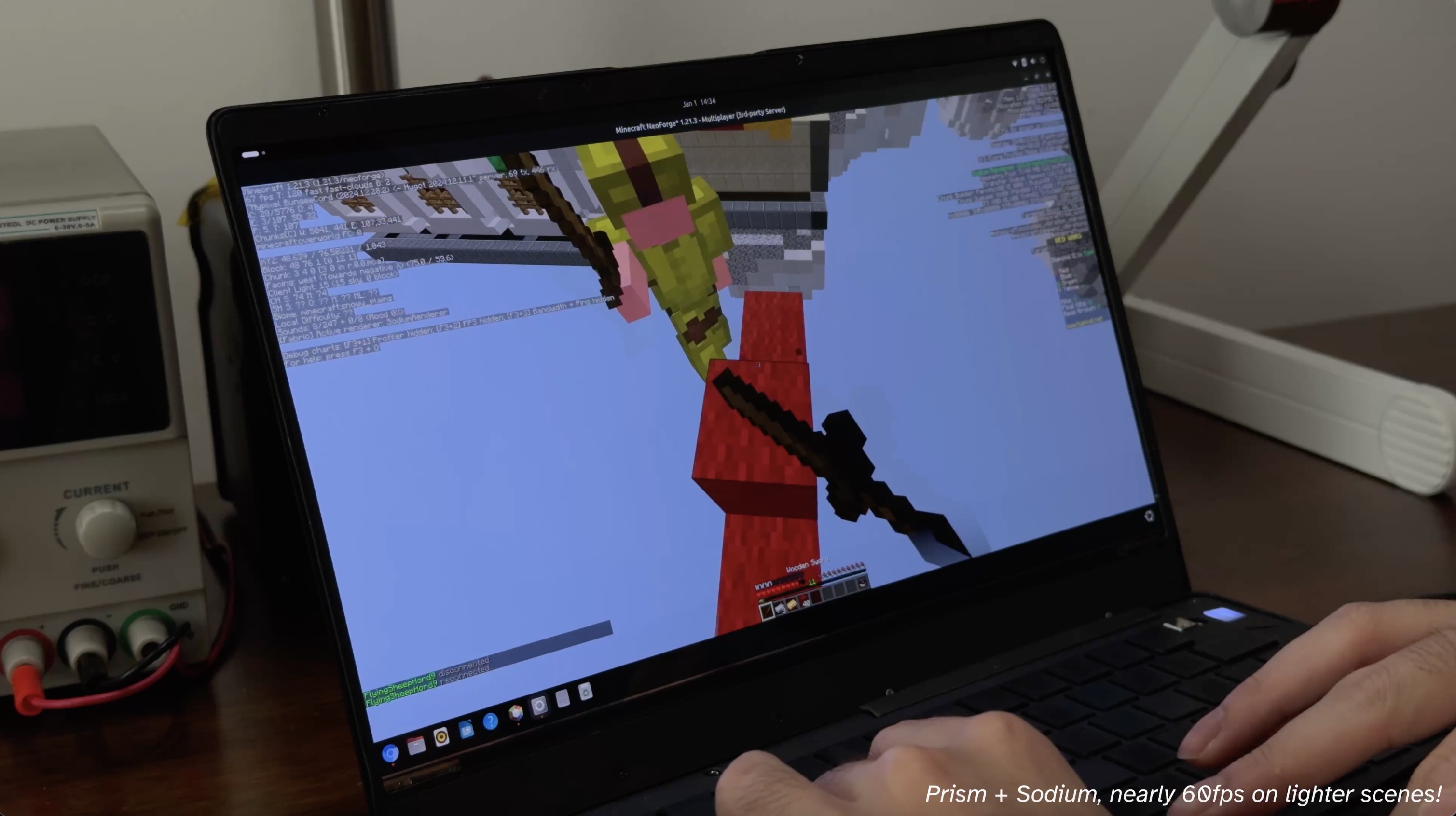
Epic Hypixel Bedwars gaming
Finding an electron in a cloud
I first made a mental map and transferred it into Obsidian:

Boiling it down, it landed me with a lofty list of goals:
- RK3588 SoC Motherboard
- CM3588-based
- USB-C USB3.1 Gen 1
- PCIe Wi-Fi/BT + SSD
- Powertrain
- ESP32-S3 embedded controller
- ~60Wh Li-ion battery pack
- Peripherals
- Wireless mechanical keyboard
- Glass-topped multi-touch trackpad
- 4K AMOLED 13.3” display
- Anodized aluminum CNC chassis
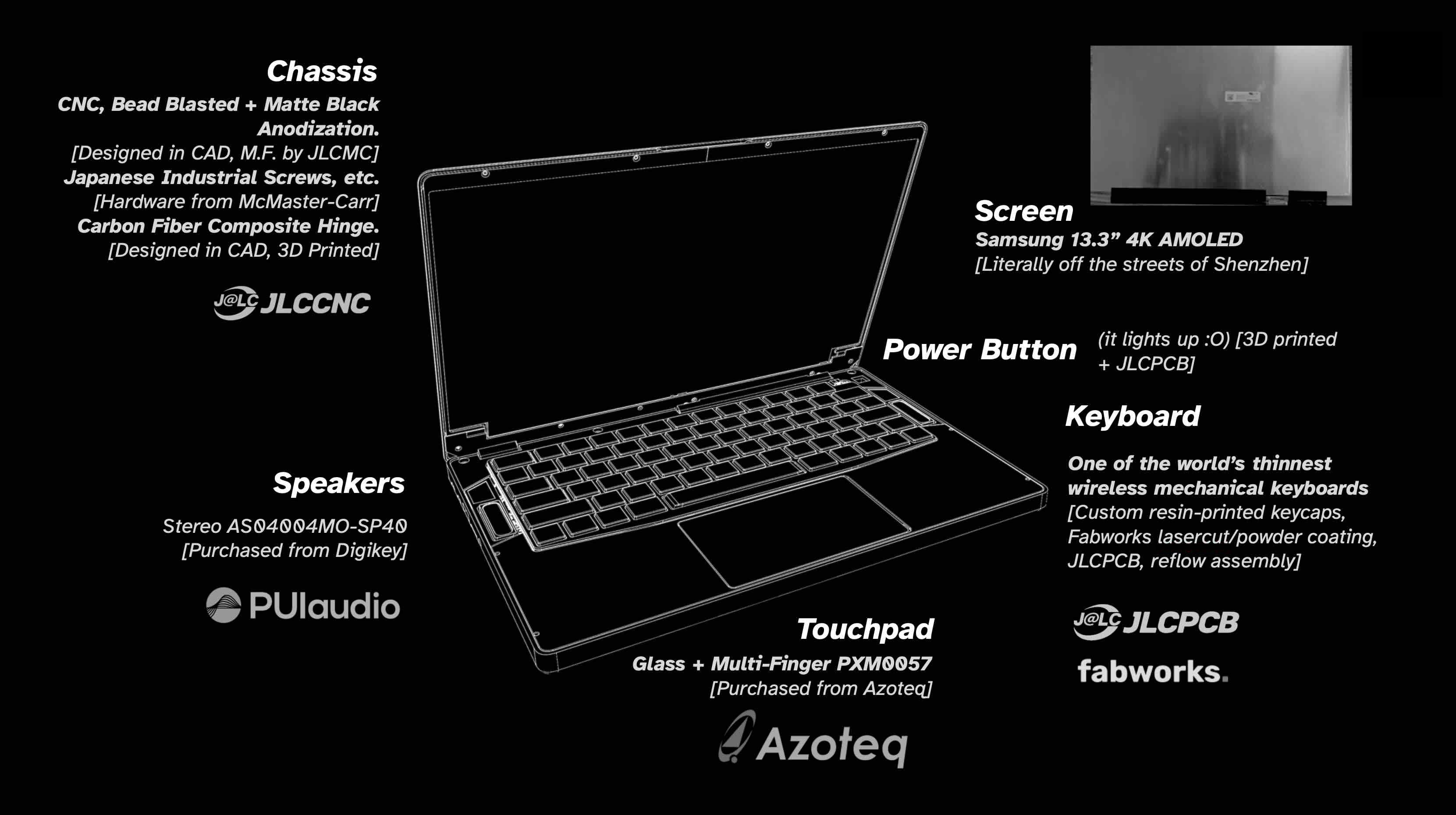
General system overview
Fermionic Analysis
Choosing the chip
I looked towards single-board computer SoCs, as board manufacturers commonly release schematics for reference. In many aspects, the Rockchip RK3588 is the fastest consumer-procurable chip on the market. Despite the spotty software support, the hardware documentation has lots of developer resources and reference schematics from SBC manufacturers.
Some quick specs:
- Quad core A76 and quad core A55
- Mali-G10 GPU
- 6TOPs NPU
- 8K@60FPS decoder
- I/O: 8K display, dual USB3.1, PCIe 3.0 x 4, HDMI2.1/eDP 1.4, etc.
With only a few months to work on this project, an SoM (system on module) like the Raspberry Pi CM5 presented the best option for its hardware compatibility and a high likelihood of a snug integration. Choosing an SoM also alleviates memory and other high-speed signaling concerns. Looking around for a RK3588 SoM, I came across the CM3588 by FriendlyElec. Cheap, well-documented, and easily procurable. Sounds good!
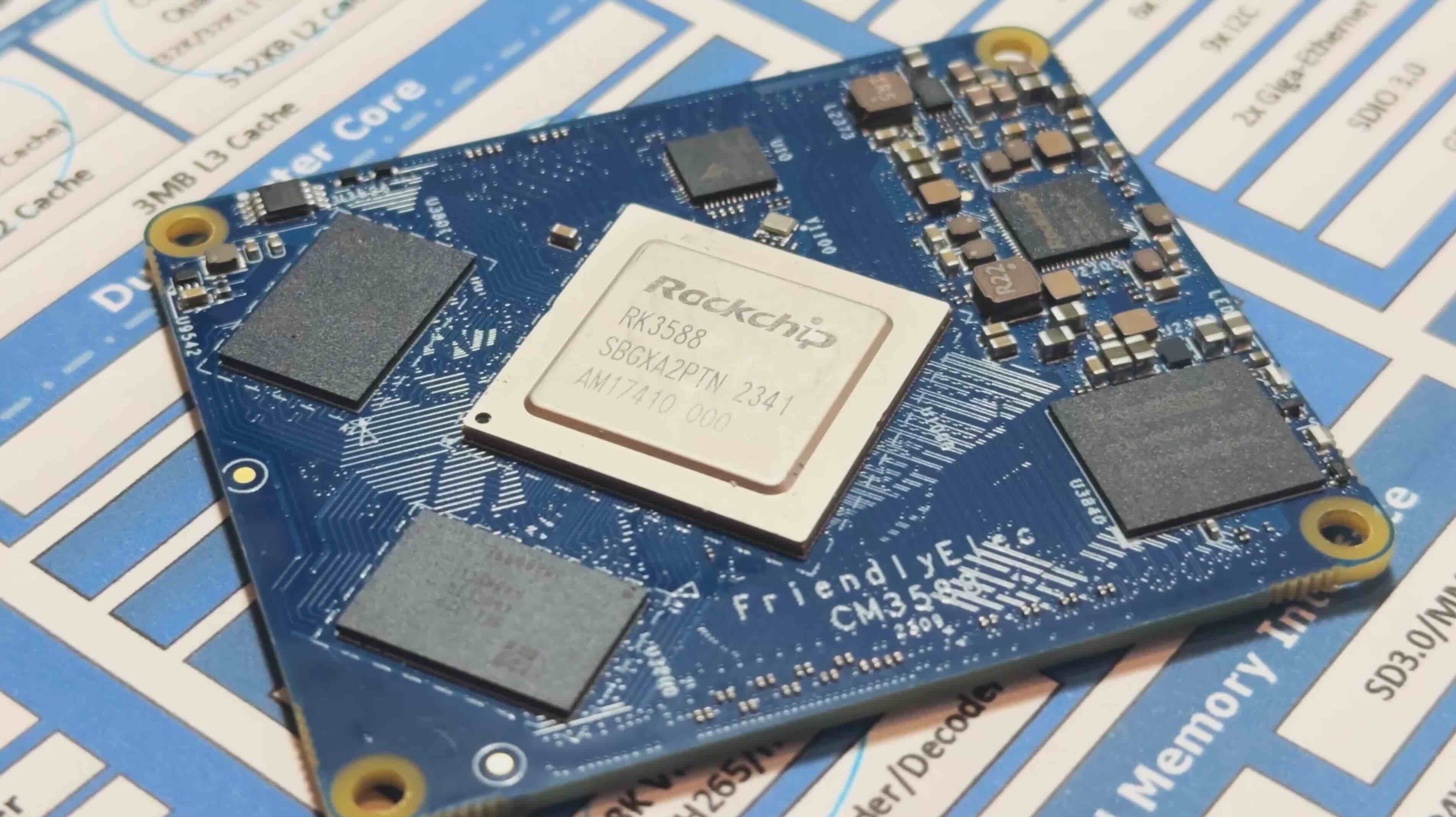
FriendlyElec CM3588 SoM
Display
I hopped on panelook.com and filtered by size and resolution. I’ve always been a sucker for high pixel density, so I went with a 4K AMOLED 13.3” display. Cross referencing stock availability on Taobao (Chinese domestic Aliexpress), the ATNA33TP11 seemed to be the one with most brand-new stock since OLED risked burn-in.
A highlight: during display evaluation, switching out a connector and shortening the board by 2mm improved signal integrity just enough for the 1.5GHz x 4 signals go pass through. Getting the display running on Linux meant finding system logs from Asus laptops that have this display, reverse-engineering the values, and tuning the power-on timings amongst other things just right. TLDR; getting a 4K AMOLED eDP display running on non-mainline Linux was a heck of a journey, so read this if you’re interested (coming soon).

ATNA33TP11 working with display evaluation board V2 short
Powertrain
The cells had to be 6mm thin and four packs lined up should take roughly half of the entire chassis volume. Chinese manufacturers don’t stock batteries readily, and shipping them to the US would be a pain. Thus, I looked on the American side. I stumbled upon with these batteries from AA Portable Power Corp. or batteryspace.com. or Powerizer. Doing the power calculations, we get: 4.250Ah 3.7V 4S = 62.9 Wh with max 8A (so max 134.4W discharge)! Solid.
The total voltage is 4.2V (peak) * 4S = 16.8V. The system’s designed for up to 20V USB-C (AKA 100W) and passed into the BQ25713 charging IC. The batteries are balanced with the BQ77915 to ensure safe charging, and the power is tracked with an LTC2943 to calculate a state-of-charge percentage. I popped in an ESP32-S3 module as the controller for everything, and set it to production.
After writing drivers and sitting on the undecipherable datasheets for days, I had the batteries charging. I successfully load tested it to around 5A and powered the full system. There’s still a lot of quiescent current (about ~50mA), but I haven’t had the time to optimize the firmware.
The USB of the ESP32 connects to the internal USB on the motherboard to feed the power telemetry over UART. A Python script and kernel module in the OS forwards it to the battery service in the kernel to display it natively.
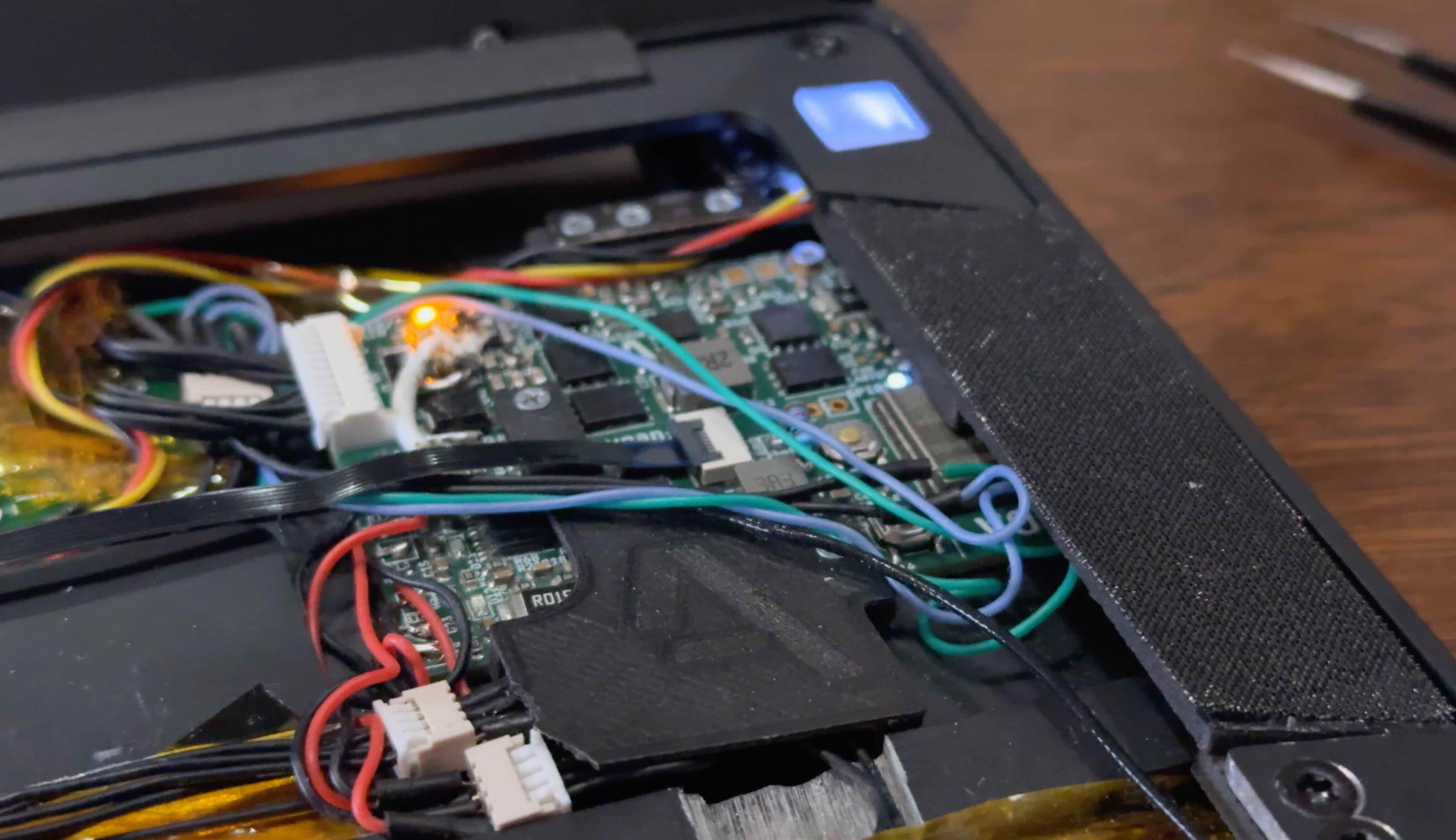
Powertrain V0.2 inside laptop
In settings, tick “Align controls with KiCad” for mouse pan/zoom/scroll
Powertrain V0.2 KiCanvas Full Link
Mainboard
With those decisions made up, I aimed for less than 90mm motherboard width based on a prelim CAD from the batteries and display dimensions.
On the physical I/O side, I settled on dual USB3.1 Type-C ports, a USB2.0 Type-A port, a headphone jack, and a microSD card slot. Internally, the M.2 E-key connects to an RTL8852BE WiFi 6 (802.11ax) + BT5.2 wireless card and the M.2 M-key accommodates up to an 2242-sized NVMe SSD. A full size NVMe SSD can fit with some modifications of the chassis too.
Tangent over, this leaves me with around ~90mm of board height. Implementing all the features on the final mainboard would stretch this writeup too long, so read this if you’re interested (coming soon).
In settings, tick “Align controls with KiCad” for mouse pan/zoom/scroll
Motherboard V1.0 KiCanvas Full Link

Mainboard B-roll shot

Detailed hardware overview
Operating on a System
Joshua Riek’s ubuntu-rockchip kernel/distro combined an out-of-the-box experience with lots of optimizations. Using Armbian’s kernel (I believe it’s still off Rockchip’s kernel) meant that it offered nearly all the features of the RK3588 on a developer-ready kernel configuration.
Since nearly all the work I needed to do was abstracted in the DeviceTree (DTS) hardware configuration language implemented with U-boot, the bootloader, I took advantage of their system-agnostic nature to speed up my trial-and-error process having never done any Linux work.
Instead of developing and compiling code on the RK3588 itself, I used my daily driver MacBook and Visual Studio Code. Once I made a change in the DTS, I’d use Orbstack (virtualization software) running Ubuntu 24.04 (shared filesystem and kernel with macOS) and compile the DeviceTree there.
DTSI, DTS, and DTS Overlay Files (some for SoC, some for other ICs, etc.) -> dtcpp binary (preprocessing & linking various DeviceTree definitions) -> dtc binary (DeviceTree compilation) -> anyon_e.dtb (compiled DeviceTree binary!)Pointing U-Boot to a custom compiled DTB (devicetree binary), I scp’ed the compiled anyon_e.dtb to the OS. A u-boot-update regenerates the bootloader configurations, and a reboot updates the changes.
That’s how I did the hardware bringup—display configurations, PCIe, USB, and other low-level system tweaks. The rest is just a standard install of Ubuntu 24.04 LTS with Linux Kernel 6.1.
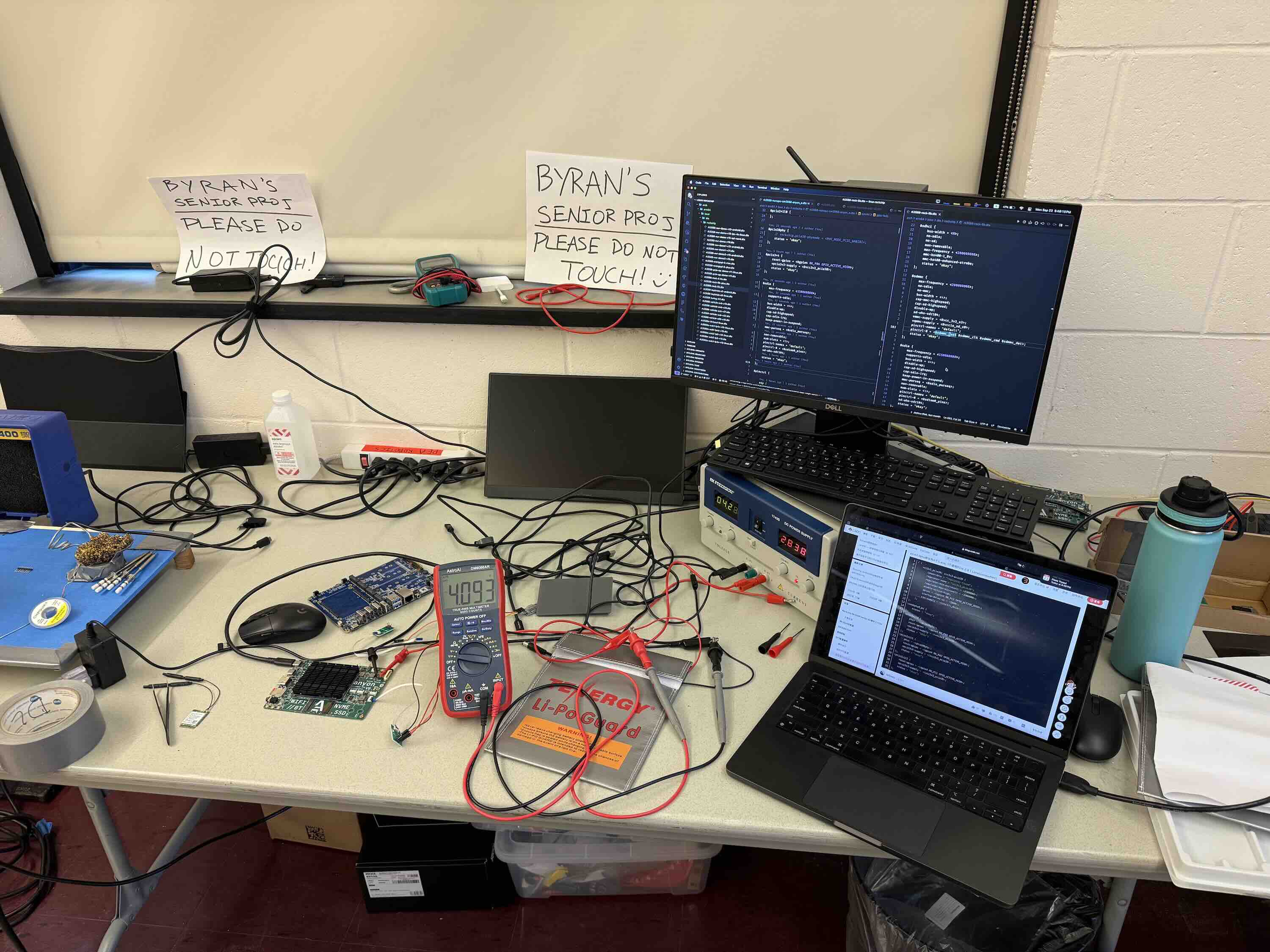
Testing batteries and writing DTS

In-depth software overview
Peripherals
Imagine being able to just pull out your laptop’s keyboard and use it as just another wireless keyboard for literally anything! Just me? Maybe.
Being a mechanical keyboard addict with quite a few ZMK keyboards designed, I chose the Cherry MX ULP mechanical switches for the best feel. Of course, a battery and fully mechanical switches add a lot of height. I used a 1mm thin 200mAh battery and a custom battery protection board that sticks up between two rows of keys to cut down on ~1.6mm (PCB height). The nRF52840 SoC running ZMK Firmware is right underneath the spacebar. A sandwich of PLA and 6061 aluminum from Fabworks crammed everything under ~7mm.
Since the keycaps aren’t easily procurable, I got a 0.15mm nozzle for my Bambu Lab X1C and printed them with PLA. It got me down a rabbit hole of tungsten nozzles, and I got quoted ~$400 for 20x 0.15mm nozzles. I’ve been thinking of trying that out too. But alas, printing out all the keycaps and assembling for the last time, the keyboard was done.
Moving on to the trackpad, it was quite quick. I knew from the start that I wanted a good trackpad, so making my own with zero capacitive tracking experience is a no-go. Searching online, I came across the Azoteq PXM0057-401 evaluation module on Mouser. It had it all—glass surface, multi-touch, and worked over USB. And, it was only 35 bucks or so. However, the trackpad has ceased production without many alternatives.
With the keyboard and trackpad working, it was time to put on the finishing touches.
In settings, tick “Align controls with KiCad” for mouse pan/zoom/scroll
Keyboard V1.0 KiCanvas Full Link
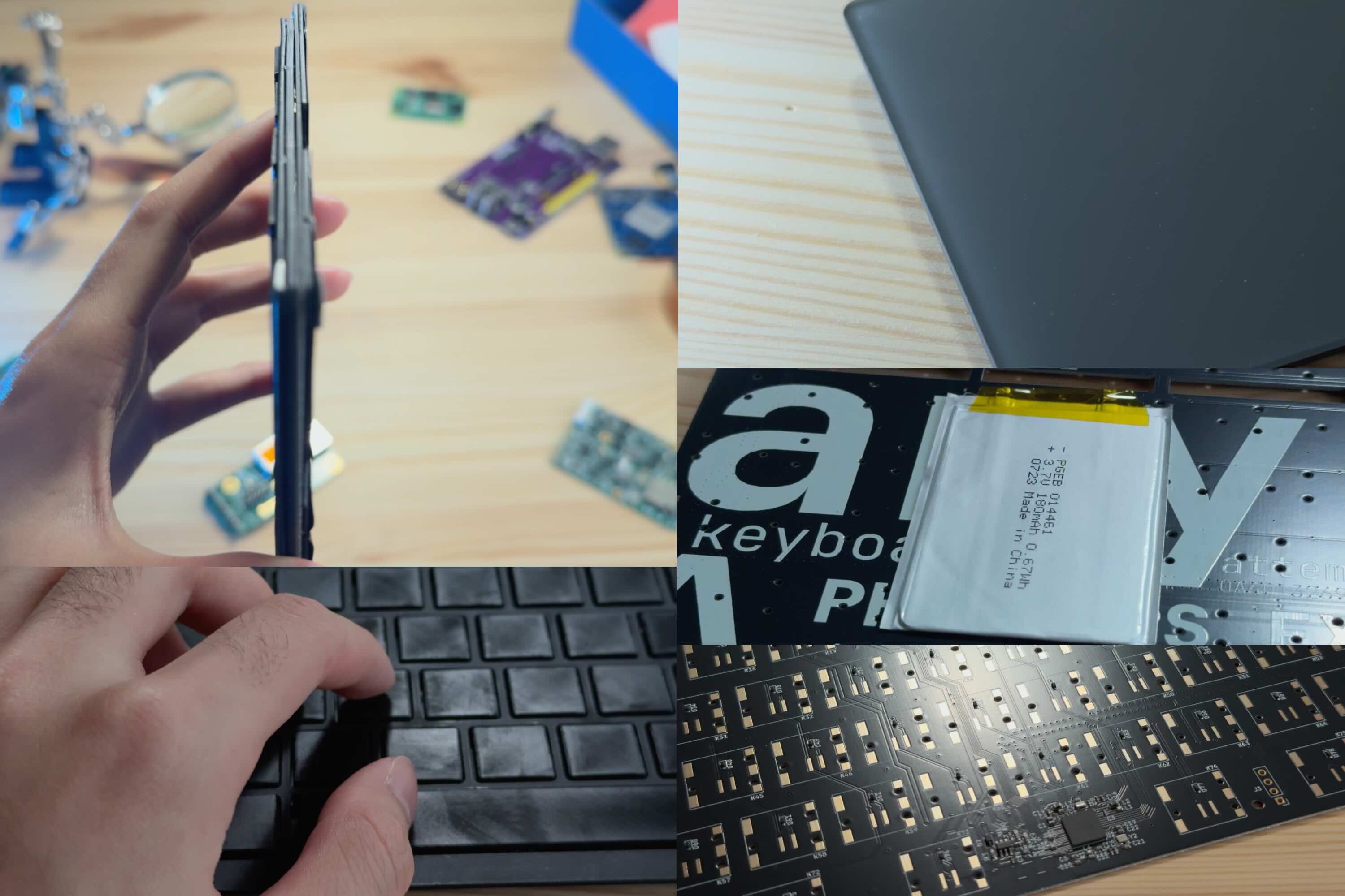
*Counterclockwise from top left: keyboard side profile, typing on keyboard, trackpad, 1mm battery on back, nRF52840 SoC area
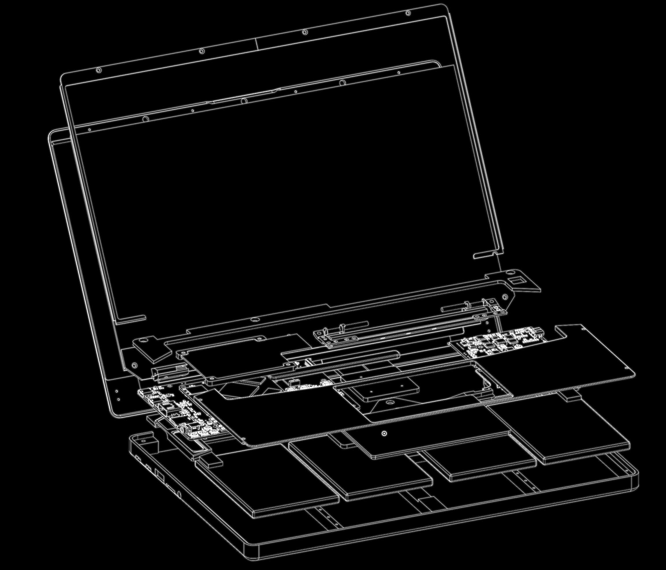
OnShape wireframe exploded view
Mechanical
Roughly the same time I began the system design, I sent a few CNC aluminum blocks off to JLC for evaluation with different anodization finishes. The dark gray anodization felt “best”, but I preferred the look of the matte black, so I settled on that. Using PTC OnShape, I (attempted) CAD’ed a robust and minimalistic look and a blend of my two favorite laptop lineup designs, the Razer Blade and the MacBook Pro. Because of the removable keyboard, the bottom has no screws. Instead, the palm rest screws into the bottom chassis. CAD Link here.
The hardest part about the chassis was the hinge. I used Framework’s 13.3” hinge because it has a 3D model. I constrained it in OnShape so I can see the exact closing angles.
The chassis layout is fairly simple: batteries on the bottom, the power board on the right, motherboard on the left, and the hinge mechanism on top. Oh, and a transparent PETG FDM printed power button that lights up on a custom PCB. To balance out the asymmetric hinge (caused by the mainboard being too wide), a little carbon fiber rod lines up on the left side too.
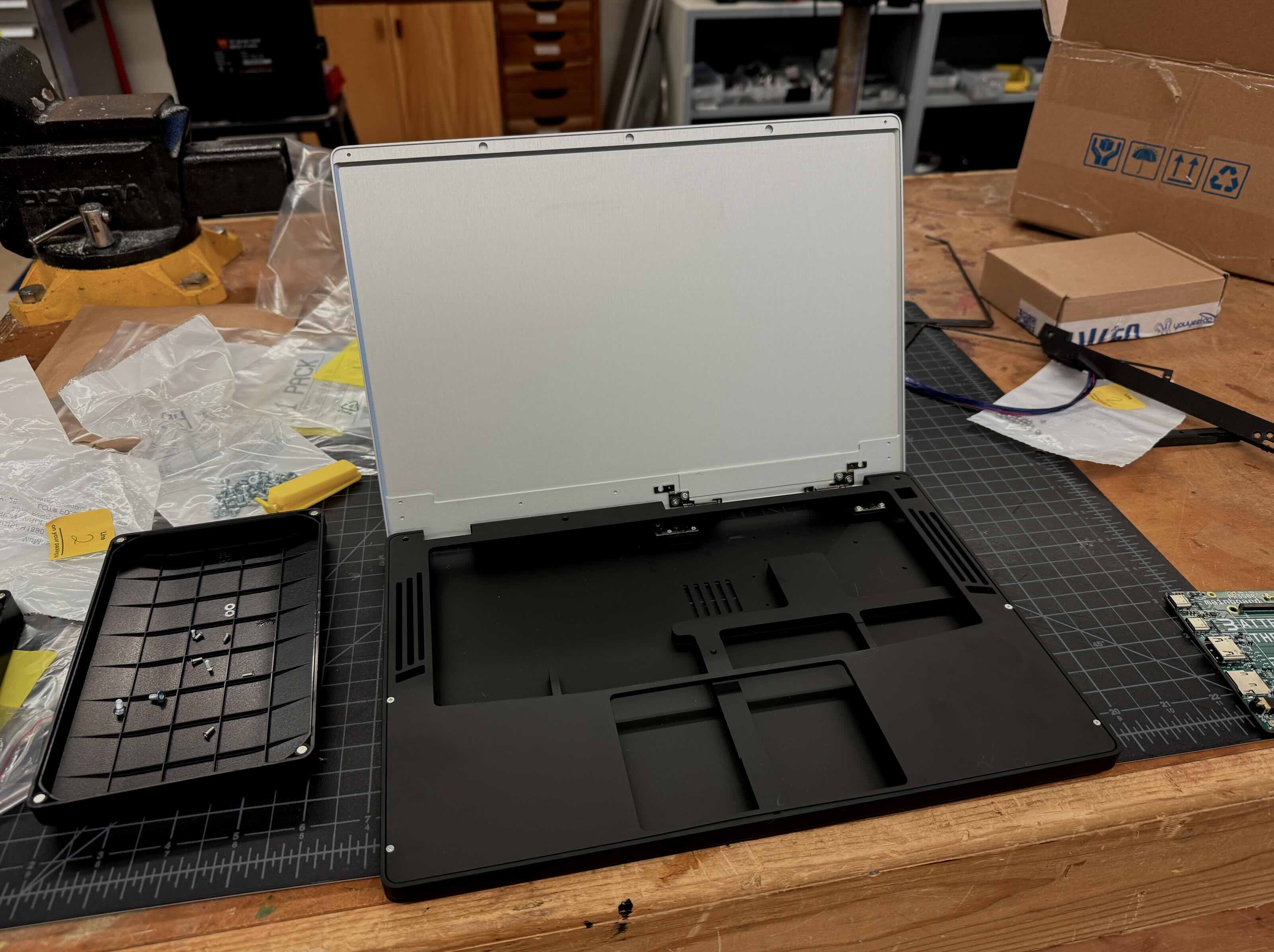
Chassis test fitting
It was a battle to get the screen assembly to not hit anything while also covering Although I started considering thermals way in advance, hence the gap here for the heatpipe to go through, I still had difficulty fitting everything in. The distance between the bottom of the keyboard and the top of the heatsink is less than a half a millimeter. The cooling system is really constrained because I don’t have the resources to make a custom heatpipe and fin solution. So, I made a full copper CNC heatsink (from JLCCNC) and a heatpipe connected to a fan. It’s all connected with PTM7950.
I also added these PUI audio speakers on either side. The audio from the CM3588’s DAC didn’t work and I ran out of debugging time, so I made a USB to audio converter board separately and shot it through an Class-D amplifier. I would’ve also made the amp, but I ran out of time.
As I reached final assembly, I used a mix of JLC’s selective laser sintering (SLS) of nylon powder and FDM printed PA6-CF for smaller structural parts. Putting it all together with the matte black CNC aluminum chassis, I finally had my laptop.

Inside full laptop assembly
Reflection
The hardest class I’ve taken so far was quantum mechanics in my junior spring term. A few months before spending hours solving time-independent and dependent Schrödinger equations, I was on the squash bus (the sport, not the vegetable). My friend suggested I make a laptop for my senior project—and that was all. I came up with the name anyon_e in June, after I finished the quantum course.
Making this laptop was hard. Mentally pressured with a deadline, and a constant inter-disciplinary challenge across electrical, software, and mechanical systems. Summing up everything I’ve ever done. It took up most of my mind from May until now.
Inspired by open-source projects like ZMK, KiCAD, Blender, and countless OSHW projects, I want to do my own little part. To put power in people’s hands in creation, innovation, imagination, or whatever else. To attempt the impossible.
Sincerely,
Byran
